Description
Virtual 16-bit processor built and tested in Verilog.
To Run:
On a shell:
-
Add instruction to run in vmem0.vmem file
> iverilog procshell.v
> ./a.out
-
Testing mode with prebuilt instructions available using
> ./test.sh
On the Icarus Verilog Web App:
-
Open Icarus Verilog and copy processor.v file into Verilog source code box
-
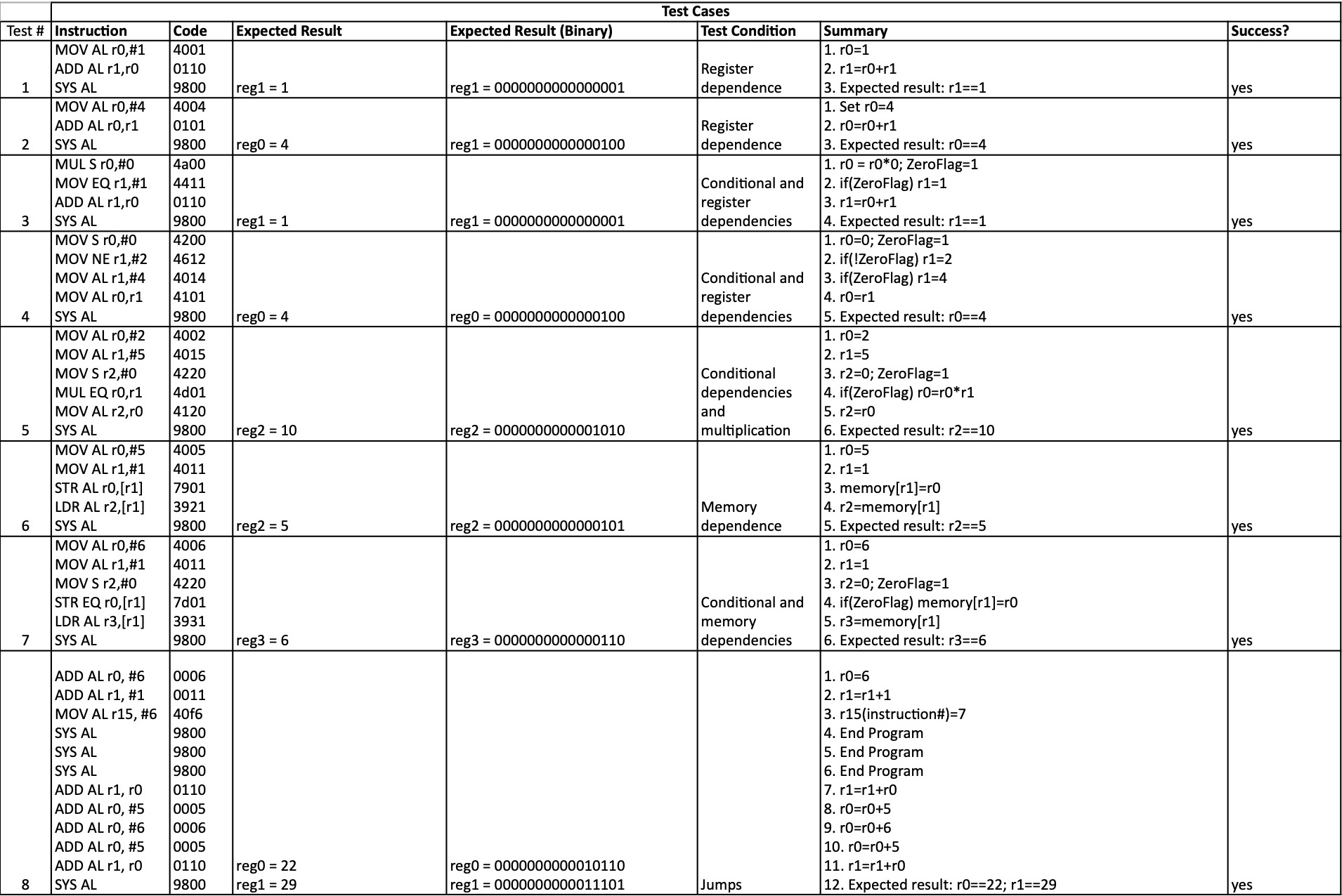
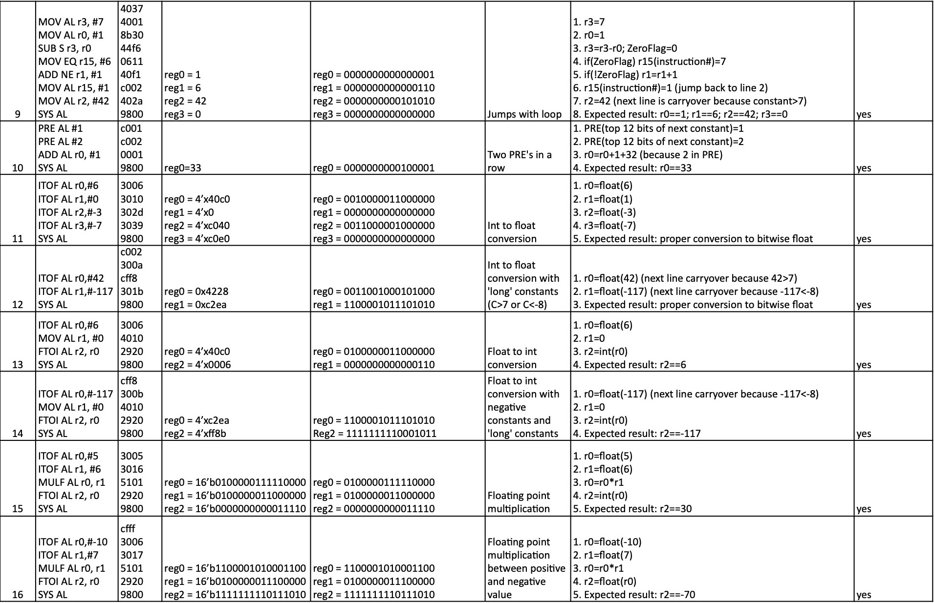
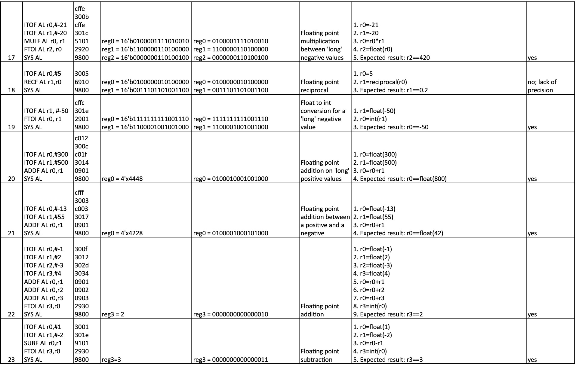
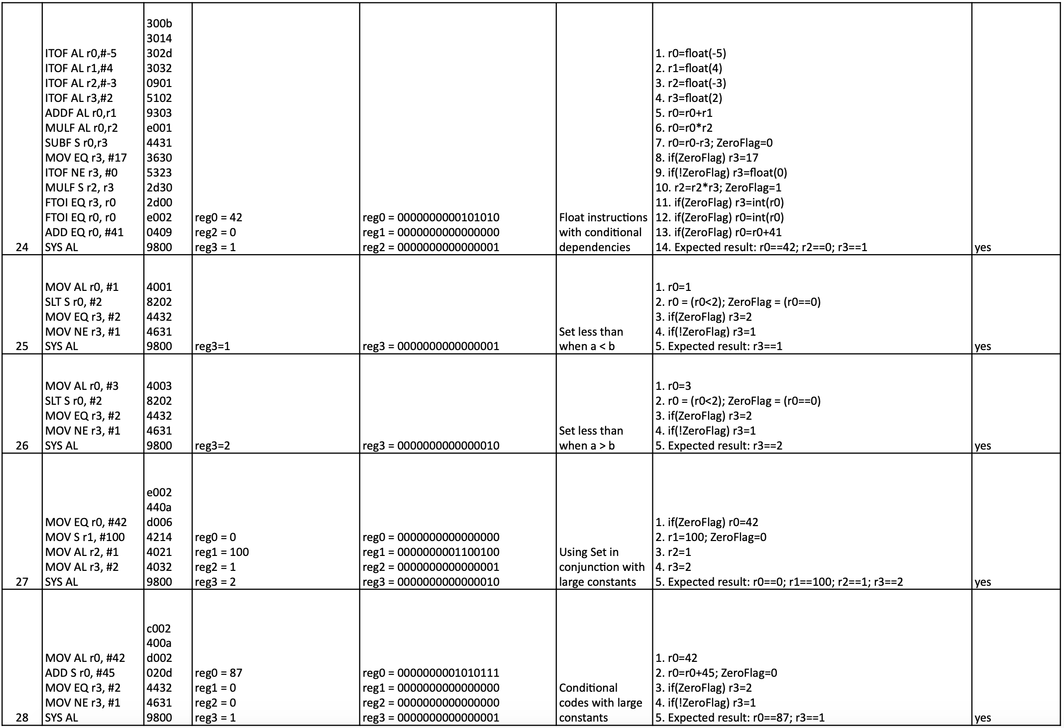
Add instruction to run in VMEM0 box. Prebuilt instructions can be found here. The instruction codes are in the code column. These are assembled using the AIK Assembler
Instruction Set
The PinKY Instruction Set was designed by Professor Hank Dietz for use by EE480 courses at the University of Kentucky. PinKY is a simple architecture based on the ARM instruction set.

Bits 0-4
Instruction Code. There are 21 different instruction codes, so these are stored in 5 bits. A full list of the codes and their functionality can be found here.
Bits 5-6
Conditional Code. This can allow the Zero Flag to be set. The Zero Flag is a one-bit flag used to make conditional statements possible in this instruction set. The Zero Flag is set to 1 (True) if the result of the previous instruction is 0, and to False (0) otherwise.
-
00: AL (Always): Always executes and does not set the Zero Flag.
-
01: S (Set): Always executes and also sets the Zero Flag to 1 or 0 subsequently based on if the output of the previous instruction was 0.
-
10: EQ (Equal): Only executes if the Zero Flag is set to 1. It does not re-set the Zero Flag.
-
11: NE (Not Equal): Only executes if the Zero Flag is set to 0. It does not re-set the Zero Flag.
Bit 7
Register Flag: 1 if the last 4 bits are a register; 0 if they are a constant value.
Bits 8-11
Destination Register: There are 16 different registers and this one is used for the computation of the instruction. The result of the instruction is then copied into this register.
Bits 12-15
Second Argument: This is either the code for one of the 16 registers or a constant value. Constant values greater than 8 or less than -7 are handled in the assembler phase and given the PRE instruction code and moved to a different instruction. This process is outlined in the subsection below.
Assembler
Statements can be translated into the instruction set outlined above using the AIK Assembler. AIK is a tool which makes it easy to build assemblers from specifications, built by Professor Dietz. More information on AIK and its functionality can be found here: AIK Assembler Interpreter from Kentucky.
Example: the instruction MOV AL r0, #6 is translated as a base-2 0100 0000 0000 0110, or a base-16 4006.
-
Bits 0-4 are set to 01000 because that's the instructional code for MOV, the move instruction:
0100 0000 0000 0110
-
Bits 5-6 are set to 00 because that's the conditional code designated for AL (Always):
0100 0000 0000 0110
-
Bit 7 is set to 0 because the second argument is a constant instead of a register. The syntax requires that all constants need to be preceded by the # sign.
0100 0000 0000 0110
-
Bits 8-11 are set to 0000 because that corresponds to the register's number 0 for r0 (Register 0):
0100 0000 0000 0110
-
Bits 12-15 are set to 0110 because that's the binary value for the constant 6:
0100 0000 0000 0110
PRE Values:
The second argument is only 4 bits long so constants are limited to values between -7 and 8. However, if constant values outside this range are required by the instruction, the assembler separates the instruction into two different ones. The first instruction is called a PRE, which keeps two bits for the PRE instruction code (11) and two bits for the conditional code. The other 12 bits represent the top 12 bits of the constant, which are then appended to the bottom 4 bits of the constant which are kept in the subsequent instruction. Therefore, it's still possible to have constant values that fit within 16 bits (between -32767 and 32768).
Multi-Stage Processing
The processor is divided into 5 stages so that instructions can be processed concurrently.
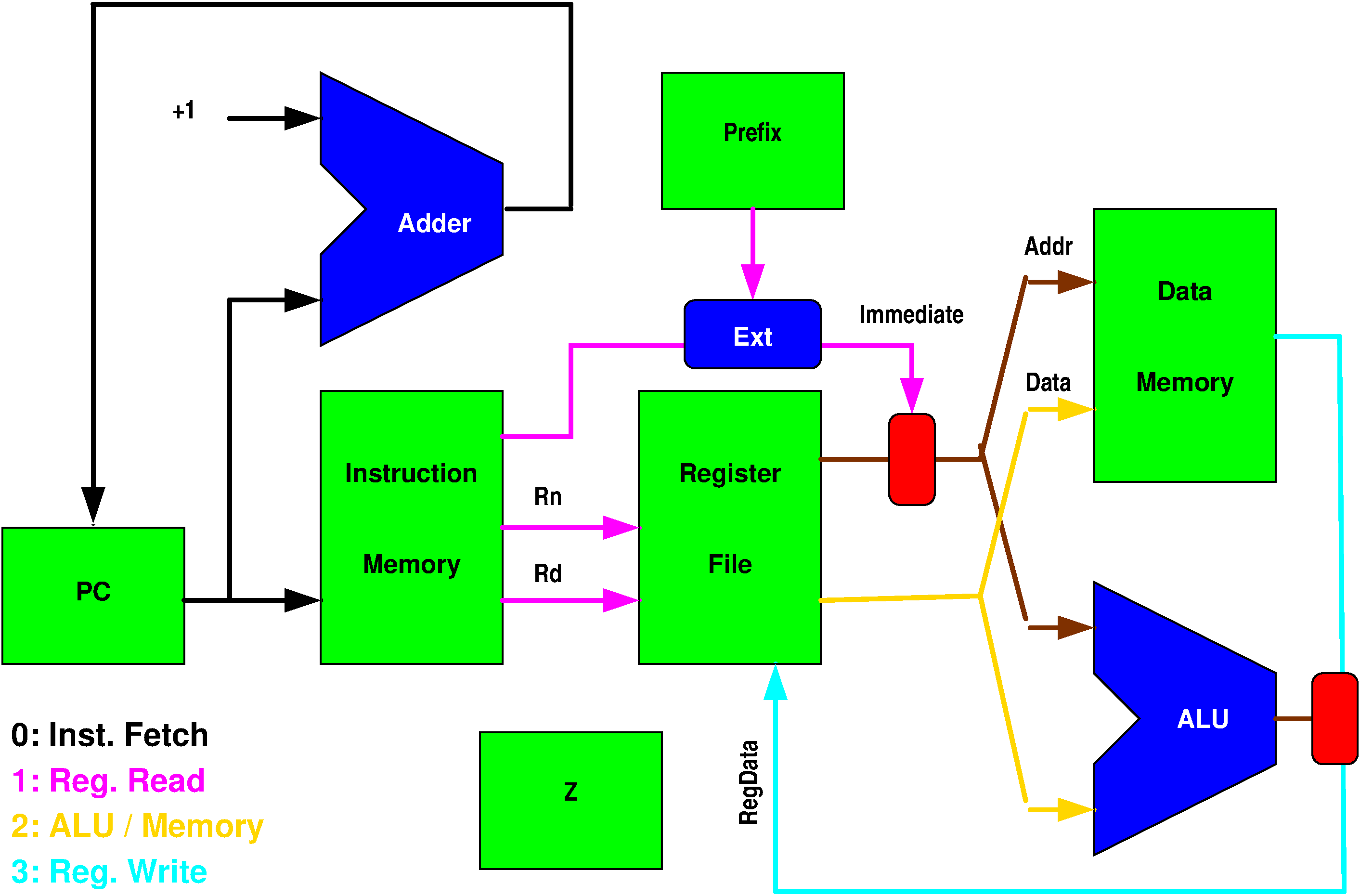
Stage 0
-
Fetches next instruction
-
Increments instruction counter
-
Writes to register from previous instruction
-
Sets value for instruction number (Register 15); used for jumps
-
Determines values for the ZeroFlag if conditional code is S (Set).
Stage 1
-
Handles dependencies by freezing instruction if it's dependent on result of previous instruction
-
Sets PRE values for constants that don't fit in 4 bits
-
Checks conditional codes to see if instruction should be processed
Stage 2
-
Decodes next instruciton
-
Sign extension
-
Reads from register (if necessary)
-
Stores negation for float conversion
Stage F
-
Proprocesses floating instructions
Stage 3
-
Arithmetic logic unit for both ints and floats
-
Computes return value
-
Stores or fetches from memory
Functionality
Conditional instructions are possible because of the two bit conditional code.
Jumps are made possible by the storing of the program counter in Register 15.
Floating point arithmetic is done within 2 clocks of the processor instead of 1 clock for the regular ALU.
Dependencies upon previous instructions are handled using a bubble method which pauses previous instructions whenever their result is required by the following instruction.
Testing
The processor can be tested through the Icarus Verilog CGI Interface or through a terminal and shell using Icarus Verilog.
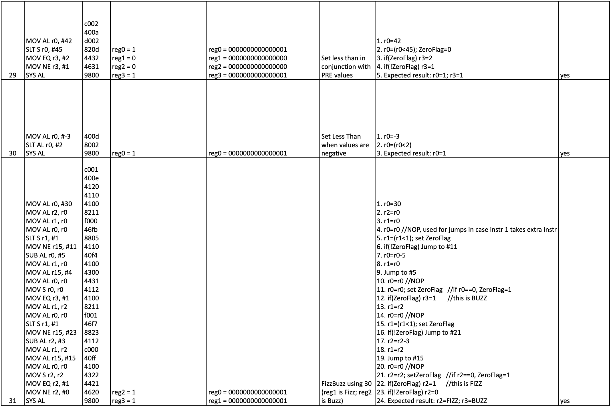
A variety of sample tests are provided below. A csv of these tests can be downloaded here
